PLC Libraries
Common Attributes and Functionality
Note
ESO PLC libraries have to be installed in the TwinCAT development environment before they can be used in projects.
Library content
For each function, e.g. lamp, shutter, motor, etc, the corresponding PLC library delivers:
- A function block (FB) for function control, e.g. FB_LAMP. Note that some libraries deliver more than one FB, e.g. Motor.library.
- A function block for the HW simulator, e.g. FB_SIM_LAMP
- A template GUI, e.g. GUI_TEMPLATE_LAMP
Input parameters
In most cases, apart from the Motor library, the configuration parameters can be given in the execution part, i.e. the FB call. This way some configuration parameters that are known that will not change, e.g. active low, timeouts, etc, can be ‘hard-coded’. Input parameters have the prefix in_. There is a mandatory input parameter called ‘in_sName’ that sets the name of the device. On PLC reboot these parameters will be set in the device configuration. However, the configuration defined in the Device Manager will overwrite the device configuration on INIT. This way, by giving input parameters the number of configuration parameters can be reduced or completely avoided but still with the flexibility of correcting any configuration parameter by the Device Manager without modifying the PLC code.
Example:
Lamp1(in_sName:='Lamp1', in_bActiveLowFault:=TRUE);
Interface with Device Manager
Device managers control the PLC device exclusively via RPC methods. There are a number of mandatory RPC methods that are common to all PLC devices. They are related to device state changes and logging. Each library, in addition to the function specific RPC methods, delivers the following RPCs:
- RPC_Init()
- RPC_Enable()
- RPC_Disable()
- RPC_SetDebug()
- RPC_SetLog()
- RPC_Stop()
- RPC_Reset()
In order to have RPC methods visible in the OPC UA address space, each declaration of an FB has to be coupled with a pragma statement {attribute ‘OPC.UA.DA’:=‘1’}.
Example:
{attribute 'OPC.UA.DA':='1'}
Lamp1: FB_LAMP;

{attribute 'OPC.UA.DA':='1'}
Lamp2: FB_LAMP;
Operational Logs at PLC Level
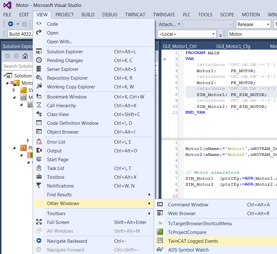
Device operations are by default logged on the PLC. The screenshot below shows how to open TwinCAT Logged Events Window.
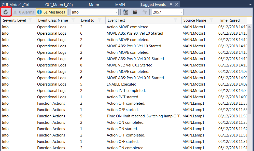
RPC methods RPC_SetDebug() and RPC_SetLog() are used to control the amount of logging information. If provided, debugging logs should be activated only for troubleshooting purpose since they could generate large amount of data.
In order to see the logs, the window has to be refreshed as shown below:
PLC simulators
In most cases the library includes a HW simulator that is linked to the device FB and gives quite realistic response. This way it is possible at a very early stage of the project to test Device Managers with a PLC. The device manager is not aware of the simulation at the PLC level and ‘believes’ that it communicates with a real HW.
Note
It is important to note that the PLC application, i.e. program MAIN, has to be modified in order to use simulators. In addition to the inclusion of a device simulator instance in MAIN, the device I/O variables have to be linked to the corresponding simulator I/O signals rather than to the real I/O.
HW simulators capture device INIT event and adjust their internal configuration ensuring that the device will work properly after the initialisation. For example, the simulator response time will be shorter than the device timeout.
Simulators provide RPC calls that are used to modify their response in order to test failure conditions of the device driver. For example, the Lamp RPC_SetFault() method can be used to set the fault signal of the lamp.
Lamp Library (Lamp.library)
FB_LAMP is the TwinCAT PLC Function Block to operate the low level control of a standard lamp device with or without intensity control.
Input parameters
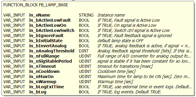
Signal Mapping
The figure below shows the TwinCAT view of the FB_LAMP I/O variables that are available for mapping to physical signals, i.e. ports of I/O terminals.
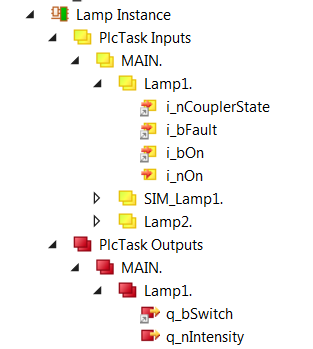
Figure 1: Example of a FB_LAMP input/output signals.
The table below describes each mapping variable.
| Variable | Port Type | Optional Mapping | Description |
|---|---|---|---|
| i_nCouplerState | UINT | No | Mapped to the ‘state’ of the coupler that hosts I/O terminals. If the terminals span over more than one coupler, it is recommended to select the ‘state’ of the last coupler that hosts a lamp signal. |
| i_bFault | Digital In | Yes | Does not have to be mapped if ‘fault’ signal is ignored, i.e. does not exist. |
| i_bOn | Digital In | No | Mapped to the Lamp status (ON/OFF) digital input signal. |
| i_nOn | Analog In | Yes | Analog feedback signal. Has to be mapped only if analog feedback is used. |
| q_bSwitch | Digital Out | No | Mapped to the Lamp control digital output signal. |
| q_nIntensity | Analog Out | Yes | Mapped to the Lamp intensity analog output signal (if exists). |
GUI Template
The Lamp Library provides a template GUI to control an FB_LAMP. Applications can easily deploy an instance of this GUI to control their own lamp function blocks by setting the GUI references to the particular instance of FB_LAMP, as shown below.
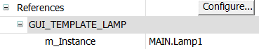
Figure 2: Instantiation of GUI_TEMPLATE_LAMP for Lamp1
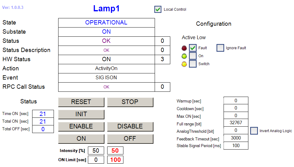
Figure 3: FB_LAMP HMI for Local Control.
Lamp specific RPC Methods
- RPC_Off() Turn lamp OFF
- RPC_On() Turn lamp ON
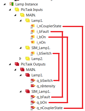
Lamp Simulator
The function block FB_SIM_LAMP implements the lamp simulator on the PLC. The simulator has the address of the lamp instance as the only input parameter. The following code shows how the simulator is declared and executed:
Declaration:
{attribute ‘OPC.UA.DA’:=‘1’}
Lamp1: FB_LAMP; // Simulated lamp
{attribute ‘OPC.UA.DA’:=‘1’}
SIM_Lamp: FB_SIM_LAMP; // Lamp simulator
Execution:
Lamp1(in_sName:=’Lamp1’,in_bActiveLowFault:=TRUE,);
SIM_Lamp(ptrDev:=ADR(Lamp1));
Simulator Mapping
Simulator RPC Methods
Shutter Library (Shutter.library)
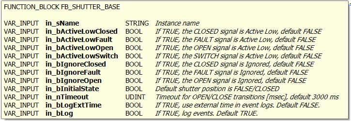
FB_SHUTTER is the TwinCAT PLC Function Block to operate the low level control of a standard shutter device.
Input parameters
Signal Mapping
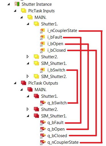
The figure below shows the TwinCAT view of the FB_SHUTTER I/O variables that are available for mapping to physical signals, i.e. ports of I/O terminals.
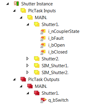
Figure 4: Example of a FB_SHUTTER input/output signals.
The table below describes each mapping variable.
| Variable | Port Type | Optional | Description |
|---|---|---|---|
| i_nCouplerState | UINT | No | Mapped to the ‘state’ of the coupler that hosts I/O terminals. If the terminals span over more than one coupler, it is recommended to select the ‘state’ of the last coupler that hosts a shutter signal. |
| i_bFault | Digital In | Yes | Does not have to be mapped if ‘fault’ signal is ignored, i.e. does not exist. |
| i_bOpen | Digital IN | No | Mapped to the Shutter ‘open’ digital input signal. |
| i_bClosed | Digital IN | No | Mapped to the Shutter ‘closed’ digital input signal. |
| q_bSwitch | Digital Out | No | Mapped to the Shutter control digital output signal. |
GUI Template
The Shutter Library provides a template GUI to control an FB_SHUTTER. Applications can easily deploy an instance of this GUI to control their own shutter function blocks by setting the GUI references to the particular instance of FB_ SHUTTER, as shown below.
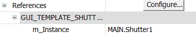
Figure 5: Instantiation of GUI_TEMPLATE_SHUTTER for Shutter1
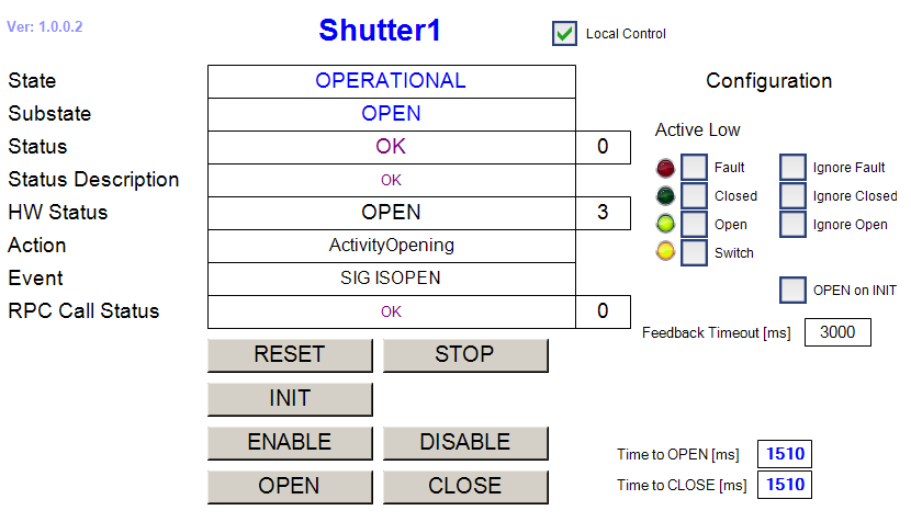
Figure 6: FB_SHUTTER HMI for Local Control.
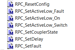
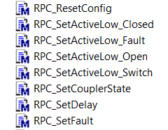
Shutter specific RPC Methods
- RPC_Close() Close shutter
- RPC_Open() Open Shutter
Shutter Simulator
The function block FB_SIM_SHUTTER implements the shutter simulator on the PLC. The simulator has the address of the shutter instance as the only input parameter. The following code shows how the simulator is declared and executed:
Declaration:
{attribute ‘OPC.UA.DA’:=‘1’}
Shutter1: FB_SHUTTER;
{attribute ‘OPC.UA.DA’:=‘1’}
SIM_Shutter1: FB_SIM_SHUTTER;
Execution:
Shutter1(in_sName:=’Shutter1’, in_bActiveLowOpen:=TRUE, in_bActiveLowClosed:=TRUE);
SIM_Shutter1(ptrDev := ADR(Shutter1));
Simulator Mapping
Simulator RPC Methods
Motor Library (Motor.library)
Warning
The Motor.library provides a number of function blocks related to motion control. For the Alpha release only discrete motion (FB_MOTOR) is fully supported and described in this document. Users should not use other FBs found in the library without consultation with ESO.
FB_MOTOR is the TwinCAT PLC Function Block used to operate motors. The library is based on the Beckhoff MC Library that is in turn PLCOpen MC compliant. This means that it should be possible to use the library for control of any type of motor, including brushless motors, under the condition that the motor controller is fully EtherCAT certified. So far, stepper, DC and synchronous motors have been tested with the library.
Usage of NOVRAM
NOVRAM is used to store and keep the configuration of the motor. The configuration of the motor is copied into the NOVRAM on every successful INIT of the motor. On power cycle of the PLC, the configuration of the motor is read from the NOVRAM during the first PLC cycle. As a general rule, only PLCs with NOVRAM should be used for motor control applications, e.g. CX-2030 that comes with 128 kB of NOVRAM. PLCs without NOVRAM can still be used for motor control applications but the configuration will be lost on every power cycle of the PLC. These applications have to rely on the higher level software that has to download the configuration after each power cycle. The other option is to hard-code the configuration in the PLC application itself.
Input parameters
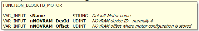
FB_MOTOR has three input parameters. Apart from the standard sName parameter for the name, i.e. the label, of the motor instance, there are two additional parameters related to the usage of the NOVRAM.
nNOVRAM_DevId NOVRAM Device ID. For PLCs without NOVRAM, this parameter should be set to zero or not given at all.
nNOVRAM_Offset Offset in bytes in NOVRAM. A motor instance needs about 500 bytes for configuration data. For simplicity it is recommended to increment offsets by 1000 for each motor. Therefore, the first motor will have the offset of zero, second of 1000, third of 2000, etc. For PLCs without NOVRAM, this parameter should be set to zero or not given at all.
The following example shows the usage of NOVRAM. It is very important to note that the entered value for the parameter nNOVRAM_DevId matches the value of the NOV-DP-RAM device. In this example the value is 4.
In case that the NOVRAM is not used, the Motor1 instance would not have any parameters and the code would look like this:
Motor1(sName:=’Motor1’);
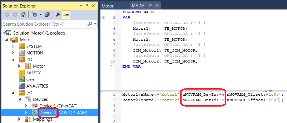
Figure 7: Application example for using NOVRAM with FB_MOTOR.
Signal Mapping
Figure 8 shows the TwinCAT view of the FB_MOTOR I/O variables that are available for mapping to physical signals, i.e. ports of I/O terminals or NC structures.
The mapping is quite different from other devices. Specific to motors, for each Axis (i.e. motor) there are two links to be established from the Axes/<Motor> Settings:
- Link To I/O… This is the link between the Axis and the motor controller terminal, e.g. EL7041, that controls it.
- Link To PLC… This is the link between the Axis and the motor instance in the MAIN program, e.g. Motor1. This link sets all the mappings for the two complex structures NcToPlc (input) and PlcToNc (output) and the user should not touch it afterwards.
The mapping parameters are described in the table below.
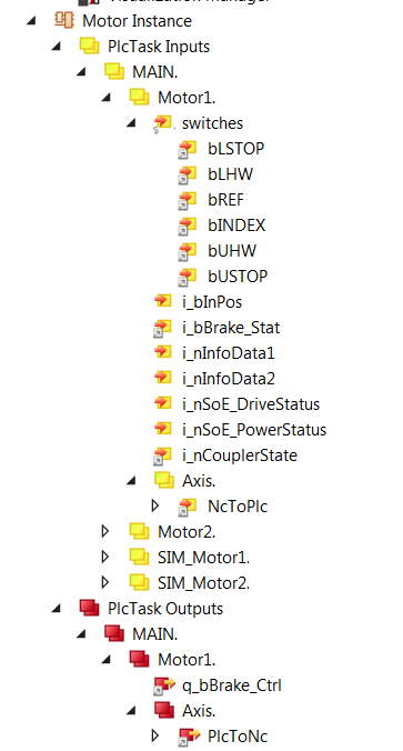
Figure 8: Example of a FB_MOTOR input/output signals.
| Variable | Port Type | Optional | Description |
|---|---|---|---|
| switches | Digital In | Yes | There are six variables to be linked to various limit and reference switches, depending on the HW configuration; upper and lower Stop and HW limits, Reference and Index switch. Switches can be linked to any binary signal (BOOL). Normally the signals are coming from digital inputs but they could also be linked to variables of type BOOL in some special applications, i.e. digitizing of analog position sensors. |
| i_bInPos | Digital In | Yes | Signal of the In-Position switch. In some applications with stepper motors without feedback (cryogenic environment) a switch is used to confirm that the motor is in correct position. |
| i_bBrakeStat | Digital In | Yes | Status of the brake feedback signal. |
| i_nInfoData1/2 | INT | Yes | Two freely selectable signed integers to be link to any variable of the same type, e.g. motor controller output current. |
| i_nSoE_DriveStatus | UINT | Yes | Serco Drive (e.g. AX5000) Status, not used with CoE drives. |
| i_nSoE_PowerStatus | UINT | Yes | Serco Drive (e.g. AX5000) Power Status, not used with CoE drives. |
| i_nCouplerState | UINT | No | Mapped to the ‘state’ of the coupler that hosts I/O terminals. If the terminals span over more than one coupler, it is recommended to select the ‘state’ of the last coupler that hosts a shutter signal. |
| NcToPlc | Struct In | No | Internal MC structure of type MC.NCTOPLC_AXIS_REF. Automatically linked from “Link To PLC”. |
| q_bBrake_Ctrl | Digital Out | Yes | Brake control digital output signal. Active low! |
| PlcToNc | Struct Out | No | Internal MC structure of type MC.PLCTONC_AXIS_REF. Automatically linked from “Link To PLC”. |
GUI Templates
The Motion Library provides two template GUIs intended for configuration and control of motor instances of FB_MOTOR respectively. Applications can easily deploy instances of the GUIs by setting the GUI references to the particular instance of FB_MOTOR_CONTROL, as shown below for the case of the configuration GUI.
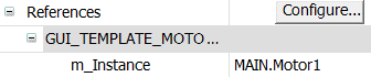
Figure 9: Instantiation of GUI_TEMPLATE_MOTOR_CONFIG for Motor1
From the Configuration GUI, shown on Figure 10, it is very simple to set axis type, define INIT sequence, select user defined methods to be executed, set the active low parameters for each switch, as well as to configure brakes, define timeouts, software limits and backlash compensation.
Once the motor is successfully initialised, all configuration will be stored in NOVRAM.
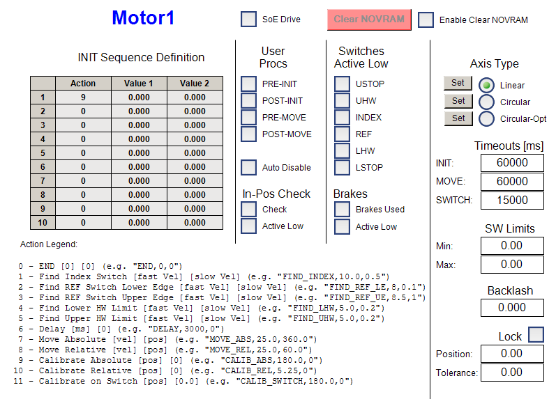
Figure 10: FB_MOTOR HMI for motor configuration.
From the Control GUI, shown on Figure 11, it is possible to perform basic control operations on the motor.
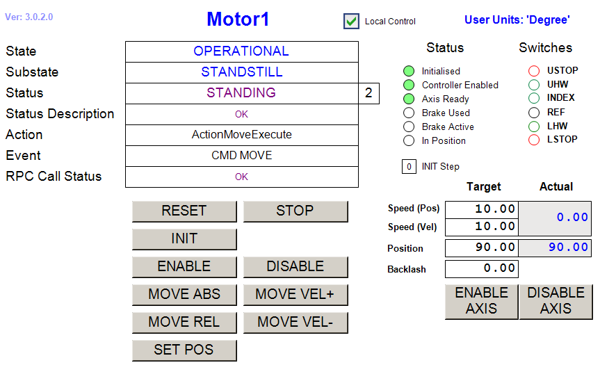
Figure 11: FB_MOTOR HMI for Local Control.
Motor specific RPC Methods
- RPC_MoveAbs() Move to absolute position
- RPC_MoveRel() Move relative to current position
- RPC_MoveVel() Move in velocity
Motor Simulator
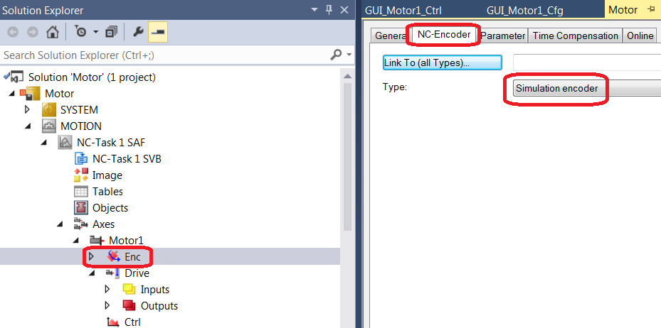
Important note: In order to use motor simulator, the Axis Encoder has to be configured as Simulation encoder, see below.
The function block FB_SIM_MOTOR implements the motor simulator on the PLC. The input parameter of the simulator are addresses of the motor instance configuration and status structures. The following code shows how the simulator is declared and executed:
Declaration:
{attribute ‘OPC.UA.DA’:=‘1’}
Motor1: FB_MOTOR;
{attribute ‘OPC.UA.DA’:=‘1’}
SIM_Motor1: FB_SIM_MOTOR;
Execution:
Motor1(sName:=’Motor1’,nNOVRAM_DevId:=0);
SIM_Motor1 (ptrCfg:=ADR(Motor1.cfg), ptrStat:=ADR(Motor1.stat));
The screen shot below shows how to configure Axis Encoder as Simulation encoder.
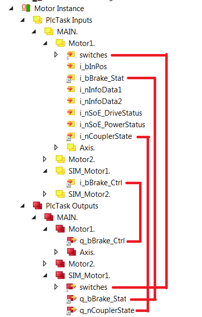
Simulator Mapping
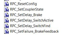
Simulator RPC Methods
User Defined Methods
The functionality of FB_MOTOR can be extended by user defined Pre- and Post INIT and MOVE methods. FB_MOTOR already includes the four dummy methods (see below) that only add a delay of three seconds during the execution. However, the dummy implementation can be a good starting point when overloading these methods for specific implementations in FBs that extend FB_MOTOR functionality.

I/O Device Library (IODev.library)
IODev.library contains a number of FBs for handling analog and digital sensors and I/O devices. In addition it provides FB methods for scaling of signals in order to work directly with temperatures, pressures, etc, instead of displaying pure voltages that cannot be easily interpreted by the user before they are scaled at the WS level. Simulators for analog and digital signals are also provided. They might be of great help at early stages of projects when sensors are not available yet or for testing of out‑of‑range conditions.
The library provides a Function Block called FB_IODEV_BASE that is intended to be extended and customised by the user. In addition, there is a Function Block FB_IODEV_SENS_8_4 that is an example how to customise a sensor device to handle eight digital and four analog input signals. This example doesn’t use the user scaling, so the scaling is supposed to be done on the WS. An example with user scaling can be found under Examples directory in the Function Block called FB_IODEV_CUSTOM_SENS_8_4 that extends the functionality of FB_IODEV_SENS_8_4 by overloading the M_UserConfigure() method.
Input parameters
User Customisation
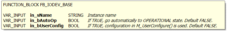
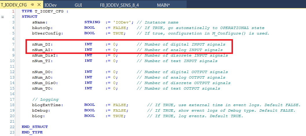
The Function Block FB_IODEV_BASE doesn’t have any signals defined but provides all methods to handle I/O signals. The FB has to be extended by the user. The extended FB has to declare arrays of analog and digital signals (or other types as well that are not completely supported in the Alpha release). In addition, it has to set the corresponding number of each signal type in the configuration of the sensor. The default numbers of various types of sensors are set to zero in the base FB, so the user has to set only the ones that are not zero.
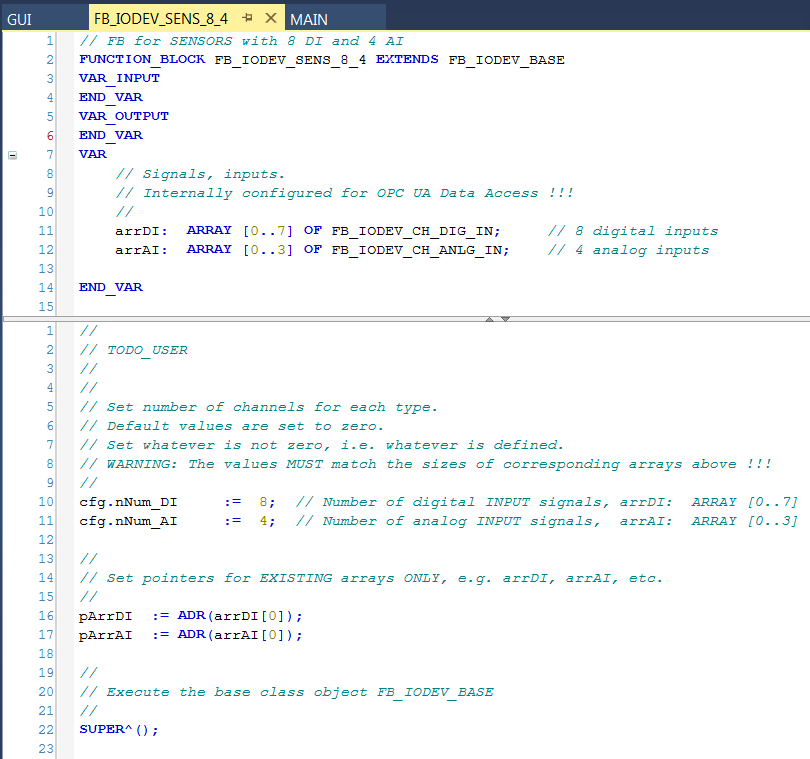
The code below shows all that the user has to do in order to define a FB that extends the functionality of FB_IODEV_BASE. It is a trivial task.
Signal Mapping
As an example, the figure below shows the TwinCAT view of the FB_IODEV_SENS_8_4 input variables that are available for mapping to physical signals, i.e. ports of analog and digital input terminals.
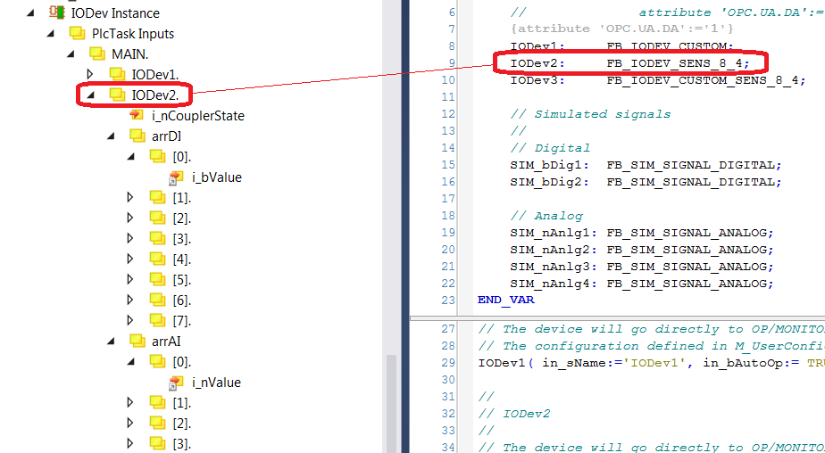
Figure 12: Example of a FB_IODEV_SENS_8_4 input signals.
The table below describes each mapping variable.
| Variable | Port Type | Optional | Description |
|---|---|---|---|
| i_nCouplerState | UINT | No | Mapped to the ‘state’ of the coupler that hosts I/O terminals. If the terminals span over more than one coupler, it is recommended to select the ‘state’ of the last coupler that hosts a shutter signal. |
| arrDI[i].i_bValue | BOOL | Yes | Array of digital input signals |
| arrAI[i].i_nValue | INT | Yes | Array of analog input signals |
GUI Template
The IODev Library provides a template GUI GUI_TEMPLATE_IODEV for FB_IODEV_BASE FB. The GUI can be also used for the Function Blocks that extend the FB_IODEV_BASE functionality. Applications can easily deploy an instance of this GUI by setting the GUI references to the particular instance of the FB, as shown below.
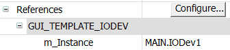
Figure 13: Instantiation of GUI_TEMPLATE_IODEV for IODev1
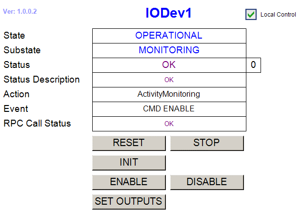
Figure 14: FB_IODEV_BASE HMI for Local Control.
IODev specific RPC Methods
- RPC_SetOutputs() Activate IODev outputs (not used with pure sensors)
Signal Simulators
The IODev.library provides individual analog and digital signal simulators. This means that if the user wants to simulate all signals of a sensor with eight digital and four analog signals, for example, he will have to instantiate eight digital and four analog signal simulators. However, for testing purposes it might be needed to simulate just a few signals. Time parameters are given in milliseconds.
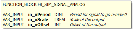
The function block FB_SIM_SIGNAL_ANALOG implements a simulated analog sinusoidal signal. The input parameters are:
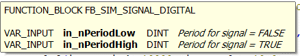
The function block FB_SIM_SIGNAL_DIGITAL implements a simulated digital signal. The input parameters are:
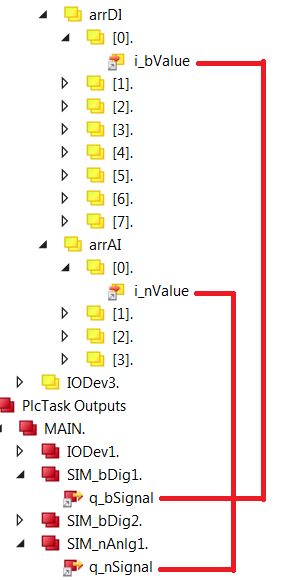
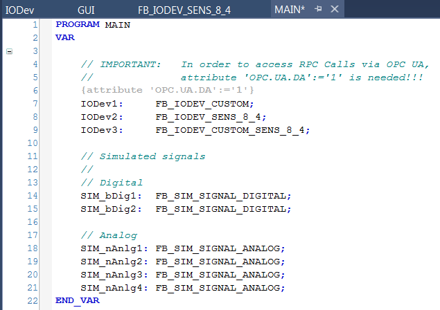
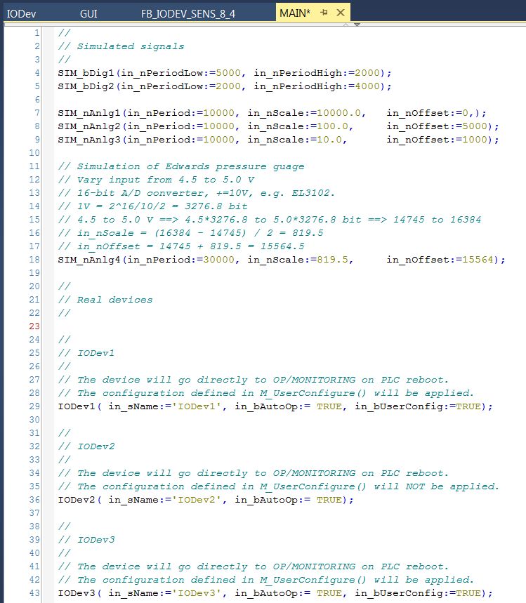
The following code example is the screen capture of the Program MAIN that is delivered with the library. The code shows how to configure sensors as well as simulators whose outputs could be mapped to sensor input variables.
Simulator Mapping